Phase 1: Single Site Injection
(December 2007 - March 2008)
Objective
- assess the grindability of the cuttings
- determine the injection behavior of the Wasatch G formation and its ability to contain the waste.
Conditions for Downhole Injection
- The wells were completed with tubing and packer. Annulus injection was not permitted.
- A cement bond log was evaluated prior to perforating to ensure the target zone was isolated above and below.
- The fracture pressure in the target zone was determined by conducting leakoff testing.
- Mechanical integrity tests on the tubing annulus were performed.
- A maximum surface injection pressure was specified on the basis of the fracture gradient of the confining strata.
- The maximum allowable injection volume was specified on the basis of formation thickness and porosity for a maximum injection radius of 660 ft.
- Logs from the injection well and offset wells were provided so the Colorado Water Resources Board could assure that the injectors were safely remote from underground sources of drinking water (USDW). Aquifers in the area extend down to around 1,000 ft TVD, thus the Wasatch G at 5,500 ft TVD was suitably distant.
- A tracer survey was utilized in the first well to determine if injected fluids were migrating out of zone.
Technique
Injection took place down the wellbore of a new well temporarily suspended at the intermediate casing, perforated, and equipped with tubing and packer.
Approximately 42,000 bbl of cuttings slurry, drilling fluid, and produced water flushes were injected. Maximum pump pressure rarely exceeded 1,000 psi, which was due entirely to perforation and tubing friction, as pressure quickly dropped to zero upon shut-in. A tracer survey indicated the injected material was confined to the depleted strata.
The central well (G3) was selected to be the injector for this first phase because it would be readily accessible during drilling of the four adjacent wells. A stage cementing tool was installed in the casing string above the Wasatch G to ensure good cement coverage above the injection zone.
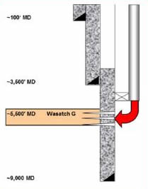
Temporary injection well schematic.
An injectivity test at 1, 3, and 6 bbl/min was conducted immediately following perforating. Pressure quickly dropped to zero upon shut-in at each rate. This indicated that fracture closure stress was below 8.9 lbm/gal equivalent. Having confirmed injectivity, the well was completed and a wireline entry guide was installed to facilitate tracer logging. The well was approved for injection service after a mechanical integrity test of the tubing by casing annulus was performed to 1,800 psi. The maximum allowable surface injection pressure was limited to the tested value.
A series of augers collected cuttings from the shaker and centrifuge discharges and transported them to the slurrification unit. The original shaker trough was left in place between the unit and the rig. When lost circulation material (LCM) was rejected by the classification shaker, it was directed down a diverter gate and transported to the cuttings trough via an auger. This rejected material was disposed of in the approved pits via the conventional method.
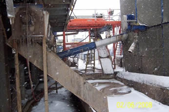
The cuttings collection system with shakers on left and slurrification unit on right.
Phase 1 Results
Over 42,000 bbl were injected, comprising 9,500 bbl slurry, 31,000 bbl of produced water flushes, and 1,700 bbl of drilling fluid. Maximum pump pressure rarely exceeded 1,000 psi and was due primarily to perforation and tubing friction as pressure quickly dropped to zero upon shut-in. Over 38,000 bbl of produced water was utilized in the flushes and slurry preparation.
A Scandium 46 tracer survey was run near the end of the program. Fifty bbl of traced slurry were slightly overdisplaced through the perforations. A gamma log indicated that the injected material was confined to the depleted strata.
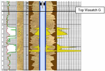
Scandium tracer survey indicating confinement to Wasatch G injection zone.
|
Phase 2: Centralized Injection Location
(October 2012 - March 2011)
The purpose of the second phase was to evaluate and overcome the logistical challenges of transporting drill cuttings from several field locations to a central process and injection facility
Objective
- Demonstrate the capability and requirements to inject cuttings from all hole sections, including surface sections.
- Establish injection well capability for increased slurry volume.
- Determine how many well sites can be supported by a single injection facility
- Gather data to forecast operability constraints for a full field application.
Technique
The well was reentered, sidetracked through a window in the surface casing, and drilled 200 ft below the top of the Wasatch G, about 118 ft into the loss zone, cased and completed for injection service with 31⁄2-in. tubing and a packer. The well was perforated from 5,580 to 5,595 ft, acidized, and injection tested. After the test, it was determined the well had to be re-perforated from 5,610 to 5,630 ft and from 5,650 to 5,660 ft to completely cover the depth where complete losses started during drilling, ~5,615-ft MD. After a final acid job, injectivity was consistent with expectations.
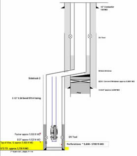
Drill cuttings injection well conversion..
Drill cuttings were transported to the cuttings processing site and discharged directly into the course processing tank using the pumping capabilities of the vacuum trucks. Additional storage was provided by two 3-sided, ~250 bbl steel troughs or boxes,.Two submersible slurry pumps transferred the wet cuttings from the receiving troughs to the course processing tank. These receiving boxes were used only when necessary.
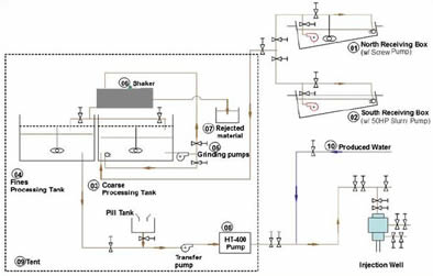
Schematic of cuttings receiving and processing circuit.
Once in the coarse processing tank, (03), the cuttings were slurrified with produced water using centrifugal dispersing pumps (05). These pumps were equipped with hard faced impellers designed for dispersing the cuttings and forming a slurry that was pumped over a classifying shaker (06). Material that passed through the screens was directed to a fines processing tank (04) where it was examined to verify the slurry properties (e.g., density, viscosity etc.) were acceptable. Viscosifier was added as necessary. Material that was rejected by the shaker (06) was returned to the coarse tank (03) for reprocessing.
“Arco Method” Dispersion:
-Hard-faced impellers with two process unit tanks of 330 bbl each.
-A shaker mounted above one tank to remove material that would not disperse -- About 10% of the cuttings processed consisted of LCM and/or surface hole rock that was too hard to disperse.
The classified slurry was pumped from the fines processing tank (04) by a transfer pump to a dual triplex injection pump (08) and pumped into the injection well. A 5 bbl high viscosity pill was pumped ahead of the slurry to prevent fingering of the slurry into the water overflush from the previous injection and 100 bbl of water were pumped after the slurry to overdisplace the wellbore . The slurry viscosity was optimized to obtain properties similar to an unweighted water based drilling fluid. When injection pressures started to climb, 1,000 bbl of water or more was pumped at high injection rates and within pressure restrictions to displace the bank of solids that was likely forming in the near-wellbore fracture.
The entire installation consisting of processing unit, cement pumps, tool storage, and pill tanks was enclosed by a tent with a 64 X 68-ft footprint, surrounded by a berm designed to contain any spills.
|
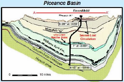 From December 2007 through April 2011, the operator conducted a two-phase drill cuttings injection pilot at the Piceance Field in Western Colorado in an effort to reduce the environmental footprint of drilling operations. This was the first subsurface injection of drill cuttings in Colorado and utilized a lost circulation zone in the Wasatch G formation as the injection interval.